Tolerance Requirements for 3D Printed Jewelry Models
Shrinkage and geometry must align with printing technology to keep cast jewelry in spec.
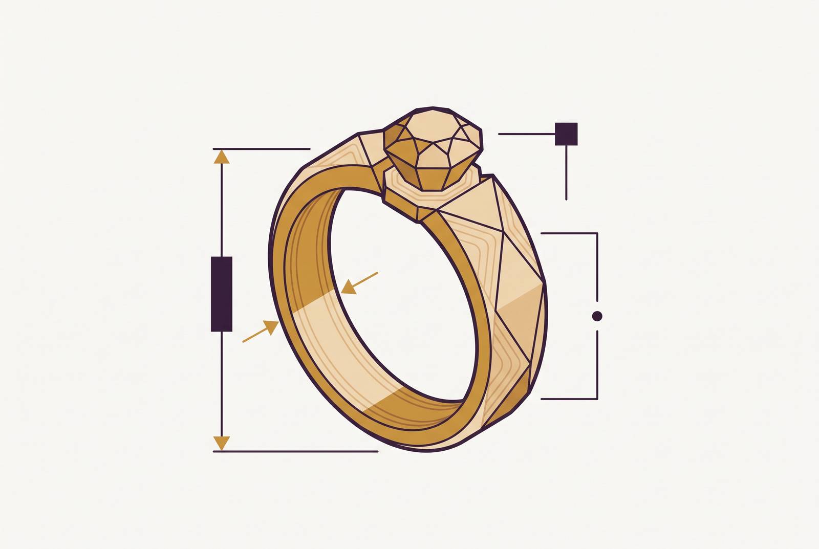
Tolerance in 3D printed jewelry is not a spec you pull from a printer datasheet. It's a budget you spend across technology, geometry, shrinkage, and stone setting. Miss any one layer and you get a model that prints beautifully but fails in production.
A tolerance is the permissible deviation between the nominal dimension in your CAD file and the measured dimension on the printed part. In jewelry, that deviation decides whether a stone seats securely, whether a prong survives setting pressure, and whether a cast ring comes out the correct size. The gap sounds small. It is small. That's exactly the problem.
Three distinct layers each consume a portion of the total allowable error. The printing technology itself determines how accurately the machine can place material. The geometry of the piece sets what wall thickness, prong diameter, and stone seat can physically survive. And the downstream process adds casting shrinkage, post-curing, and setting operations that each shift the dimension a little further.
Here's the compounding part. A small error at each layer adds up to a part that is dimensionally out of spec at the finished-piece stage even if every individual step was "within tolerance." Each step performed exactly as promised. The ring still doesn't fit. That's what makes tolerance a stack, not a setting.
Think of it like three people each taking a tiny slice off a cake. Each slice is perfectly reasonable on its own. But after all three, there's no cake left for the guest. The design process has to anticipate every slice before the first cut is made.
How the choice of printing technology sets the outer boundary of what is achievable
Each 3D printing process runs on a different physical principle, and that principle sets an accuracy ceiling no amount of careful design can exceed. You can model a stone seat to within a micron in CAD. The printer will still only be as precise as its physics allow.
FDM is the obvious starting point because it's cheap and sits on many designers' benches. Molten plastic shrinks as it cools and creates visible layer steps. RapidDirect's 2026 guide puts FDM tolerances at ±0.2 to 0.5 mm, which makes it fine for prototypes and enclosures. Fine jewelry casting patterns are a different story.
SLA works differently. A UV laser cures liquid resin with a spot far finer than an FDM nozzle. That produces significantly tighter tolerances and a smooth surface finish. The same RapidDirect 2026 guide identifies SLA as the most accurate plastic 3D printing technology at production scale, suited to dental models, jewelry casting patterns, and fine mechanical parts.
SLS and MJF sit in the middle. Both fuse nylon powder, SLS via laser sintering and MJF via fusing agents and infrared radiation. Neither requires supports, so there are no support-removal marks. The tolerance range runs comparable between the two for most part sizes. Useful for wearable forms, yes. Standard for castable jewelry patterns, no.
SLM is the metal route. It fully melts metal powder with a high-power laser, which generates significant thermal stress requiring stress relief after the build. It's relevant only for direct-metal jewelry production at high cost. Not a casual option.
Layer height and surface finish follow the technology choice. SLA can reach layer heights as low as 25 microns, producing smooth surfaces that require minimal post-processing before casting. That matters when the model goes into a mold.
So here's the practical consequence. A designer who selects FDM because it's available on the bench is not making a tolerance trade-off. They are opting out of fine jewelry production tolerances entirely. The technology choice is the first design decision, not an equipment procurement question.
The structural geometry requirements that must be met before printing begins
Before a single tolerance number gets applied, a jewelry model must meet minimum geometry thresholds. These thresholds come from the physics of the material and the demands of the setting operation. They are not negotiable. No printer can save a wall that is too thin to exist.
Start with minimum wall thickness. Rings and pendants need at least 0.8 mm. Prongs can go no thinner than 0.6 mm in diameter. For wax-pattern printing, the numbers shift by metal: minimum 0.4 mm for gold, 0.6 mm for platinum.
Prong and bezel geometry has its own numbers. Prongs should be modeled 0.6 to 1.0 mm thick. Bezels need 0.5 to 0.7 mm walls. The overall target on these features is 0.1 mm tolerance. That's the bar for dimensional control once the geometry itself is sound.
The structural argument matters because walls below these thresholds are too thin to survive the mechanical stress of stone setting. It doesn't matter how precisely they were printed. The part may be dimensionally correct and still fail in use. Precision cannot substitute for material that isn't there.
Mesh integrity is a geometry requirement too, not just a file-format issue. Non-manifold edges prevent a slicer from determining inside from outside. The result is unprintable or incorrectly printed geometry. Walls that appear correct in a render may be hollow or open in the actual mesh. If the slicer can't tell which side is which, your tolerance math is happening on a model that doesn't really exist.
Shrinkage as the cumulative error that compounds across every step from print to cast
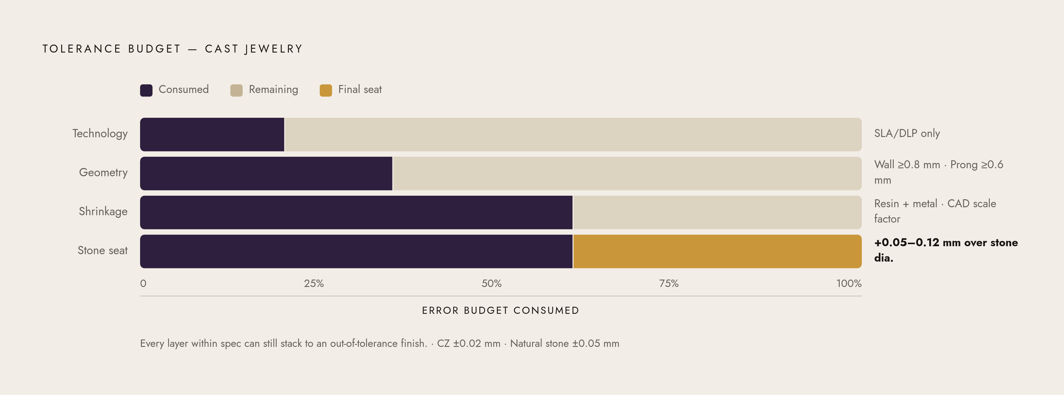
Shrinkage is where the layered nature of tolerance becomes a real production risk. It's not a single event but a compounding effect. The printed model and the casting process each introduce their own dimensional change. Failing to account for both at the design stage is the most common cause of sizing errors and stone loss in cast jewelry.
Two shrinkage sources stack on top of each other. The first is the castable resin itself. Most high-quality castable resins introduce some shrinkage. At the precision end, combining high-resolution printing with a very low-shrinkage castable resin eliminates geometric deviation and ensures consistent, zero-residue burnout for high-volume production. The resin choice is doing real tolerance work here.
The second source is metal casting shrinkage. The casting process itself introduces additional dimensional change as the metal cools. Experienced jewelers compensate by scaling the 3D model up by the appropriate percentage before printing. The compensation has to happen in CAD. By the time the casting comes out small, the fix is a reprint, not an adjustment.
Metal-infused and sintering workflows require more extreme compensation. Isotropic shrinkage compensation in CAD using a scale factor calibrated per alloy is required to retain gemstone seats and press-fit tolerances. Calibrated per alloy. That's the part designers miss when they grab a generic scale factor from a forum.
Post-processing compounds the problem further. Post-curing and sanding can significantly impact dimensions and surface quality. Every hand operation eats a little more of the budget.
The business consequence is blunt. When shrinkage compensation is not applied, the result is stone loss, rework, and customer returns. These are not abstract quality metrics. They are expensive, visible errors that end up on a bench and in a disappointed customer's hands.
Stone seat tolerances and why they require their own set of numbers
Stone seats are the one feature in a jewelry model where the tolerance must account for the physical variation of the stone itself. Not just the printer or the casting process. The stone arrives with its own dimensional uncertainty, and the seat has to absorb it. That means a different set of numbers applies.
For a secure snap-fit, stone seats should be modeled 0.05 mm to 0.12 mm larger than the stone's actual diameter. That range exists because stones themselves vary. Calibrated stones such as Cubic Zirconia carry a tolerance of ±0.02 mm. Natural stones may vary by ±0.05 mm. Your seat tolerance must accommodate the stone's own variation, not just the printed model's.
Stone-in-place casting, or SiP, adds a temperature constraint that interacts directly with seat design. Only stones that can withstand high casting temperatures work here. Diamonds, sapphires, rubies, garnets, and cubic zirconia are compatible. Mohs hardness alone does not determine suitability. Thermal stability and stone quality are the key factors.
Heat-sensitive stones such as opals cannot be used. Emeralds can be cast in place with strict temperature control, though they are not recommended for high-production runs. The seat geometry must therefore also flag which stones are physically compatible with the intended workflow. You can design a perfect seat for a stone that can't survive the process. That's a different kind of failure, and it happens more than it should.
The narrow end of the seat tolerance is too tight: the stone cannot be set without deforming or cracking the prong. The wide end is too loose: the stone rattles or falls out after setting. No single seat tolerance threshold has been established in authoritative industry sources as producing zero stone loss in production. Tolerances vary by setting type, metal, and stone size. Anyone who tells you one magic number exists is selling something.
Where AI-generated models introduce new tolerance risks — and where they do not
AI-generated jewelry meshes collapse ideation time from hours to minutes. That part is real, and it's genuinely useful. But they introduce a specific class of tolerance failure that is structurally different from the errors a trained CAD modeler makes. And harder to catch visually.
Three failure modes show up most often. Non-manifold edges, first. The slicer cannot determine inside from outside, producing unprintable geometry that looks correct in a render. A designer sees a beautiful ring on screen. The slicer sees a shape with no volume.
Inconsistent wall thickness is second. This causes shrinkage cracks at the casting stage, because thin spots behave differently from surrounding material under heat. The render looks smooth. The casting comes out with cracks that make no sense until you inspect the mesh cross-section.
Insufficient stone-seat geometry is third. Prongs that look visually correct may lack the structural depth to hold a stone under setting pressure. The AI generated something that looks like a prong. It didn't generate something that functions as one. These failures are structural and silent until the moment of failure.
The hybrid workflow that addresses this is straightforward. AI at the front for concept and first file. CAD at the back for manufacturing prep. Specify technical parameters such as stone dimensions, prong configuration, and metal weight targets before generating, so the AI output is constrained to what can be manufactured. The AI doesn't set its own rules. You set them first.
STL export discipline applies regardless of how the model was generated. Export with 0.1 mm chordal tolerance, 1 to 5° angle deviation, and 0.5 mm max edge length for high-fidelity meshes. These are not AI-specific requirements. But they become more important when the upstream geometry is AI-generated and has not been built from verified parametric constraints. A trained modeler's file carries those constraints implicitly. An AI mesh doesn't.
Parametric and AI-assisted platforms that enforce tolerance rules at the generation stage reduce the manual audit burden significantly. They keep stone size, prong geometry, shank thickness, and minimum tolerances within manufacturable bounds as part of the configuration logic. This is the design philosophy behind platforms such as AI-to-CAD tools active in 2026 that target production-ready output rather than mesh visualization. The goal is a file that can be manufactured, not a picture that can be admired.
Applying the full tolerance stack in practice: what a production-ready model actually requires
A model that is production-ready for cast jewelry has satisfied every layer of the tolerance stack. Technology selection, minimum geometry, shrinkage compensation, and stone-seat accuracy. A failure at any one layer means the piece cannot go straight to manufacturing, regardless of how well it performed at every other layer. Production-ready is a specific, verifiable condition, not a general aspiration. Here's what it looks like, layer by layer. Technology: SLA or DLP castable resin printing, or wax-pattern printing for platinum minimums. FDM is not a production path for fine jewelry. Geometry: all walls, prongs, and bezels above their material-specific minimums. Mesh watertight and manifold-clean before export. Shrinkage compensation: scale factor applied in CAD before printing, calibrated to the resin shrinkage rate and the casting alloy. Not corrected after the fact. Stone seat: modeled 0.05 to 0.12 mm over stone diameter, prong diameter adjusted for resin shrinkage, stone compatibility with SiP workflow confirmed if applicable. STL export: 0.1 mm chordal tolerance, 1 to 5° angle deviation, 0.5 mm max edge length.
There's a verification step that collapses iteration faster than any spec sheet. Request a finished sample before committing to a production run. A single cast sample resolves questions about surface density and porosity limits that no document can answer. It confirms the full stack, not just the printed model.
The business implication cuts across all of it. Getting the tolerance stack right is not a quality-control exercise performed after design. It is a design methodology applied from the first file. Platforms that enforce it parametrically make production-readiness a default rather than an outcome that depends on the designer's individual expertise. That's the difference between a bench filled with rework and a bench filled with jewelry.