What Casting Houses Actually Check Before They Accept a Jewelry CAD File
Casting houses reject files for fixable reasons—here's what they actually verify.

If you've ever exported a CAD file, felt a quiet sense of pride, and immediately emailed it to a casting house thinking your job was done, you know exactly where this article starts.
Actually, scratch that. No em-dashes. Let me say it plainly: "Done in CAD" and "ready to cast" are not the same moment. They are nowhere near the same moment.
Think of it this way. Finishing a CAD file is like writing a recipe. Sending it to the casting house is like handing it to a chef who will tell you whether your kitchen actually has the equipment to make it. Casting houses run a formal intake review before a file ever touches a printer or mold. If your file fails that review, you're looking at rework, delays, and sometimes a full redesign from scratch.
That's not a worst-case scenario. That's Tuesday.
Every item on the intake checklist maps to a specific failure mode: a hole too small causes a resin trap, a wall too thin causes an incomplete pour, a non-manifold mesh causes a slicing error. The checklist exists because real things go wrong when it gets ignored.
The accepted format list is short. STL and 3DM are universally accepted. OBJ works at some houses. STEP is available on request at a small number of shops. That's basically the whole menu.
STL is the default preference at most casting houses, and some houses accept only STL and nothing else. The reason is blunt: STL encodes surface geometry as a triangulated mesh, which is exactly what slicer and CAM software consume. It's already in the language the machine speaks.
But here's the thing about STL that catches people off guard. It carries no unit or scale data. Only surface geometry. If you export your file in inches when the house expects millimeters, the file will print at the wrong size and nothing will flag the error. The geometry looks fine. The math is just wrong by a factor of 25.4. The file is technically correct, which is honestly the worst kind of correct.
Some houses require a single-shell STL measured in millimeters as a baseline condition. Anything else is grounds for rejection before any geometry review even begins.
3DM files (Rhino's native format) are useful when the casting house needs to make adjustments on their end. STL is the right call when the file is truly final and you're confident in the geometry. Your export settings matter as much as your modeling. Unit, scale, and shell count need to be verified at export. Not at design completion. At export.
Mesh integrity: the geometry check that stops most amateur files
This is where a lot of files die.
The mesh must be watertight. No holes. No exposed naked edges. A naked edge means there's a gap in the surface geometry. The slicer hits that gap and doesn't know what to do with it, which causes errors that make the print either fail or come out wrong.
Every edge in the mesh must be shared by exactly two faces. That's the definition of manifold geometry. If an edge is shared by one face, or three faces, the geometry is non-manifold. A 3D printer requires completely unambiguous instructions on what to print. Non-manifold geometry is ambiguous. It won't slice correctly.
All components must be booleaned into a single unified part. If you built your ring shank and your head as separate objects and left them that way, the casting house's software will treat them as intersecting geometry and produce incorrect output. Boolean union them. One object.
Some production platforms process only one shell per file. Multiple shells get treated as intersecting geometry, which produces incorrect output. Single shell, unified, watertight, manifold. That's the standard.
A few other mesh issues that cause immediate rejection:
- Self-intersecting geometry
- Degenerate triangles (triangles with zero area or near-zero area)
- Inconsistent normals (some faces pointing inward, some outward)
- Faceting artifacts from a low-resolution export
On that last point: wax printers operate at very high resolution. They will faithfully reproduce every facet and flat spot on a poorly exported mesh. When converting from a 3DM to STL, set maximum distance edge-to-surface to 0.01. Triangles should not be visible at print resolution.
Tools like Netfabb and Magics RP can verify and in some cases repair mesh issues before submission. Use them. Catching problems yourself is free. Paying the casting house to fix your file is not.
Wall thickness minimums by material and feature type
General principle: CAD wall thicknesses need to be thicker than hand-fabrication equivalents. Printing, casting, cleanup, and polishing all remove material. Design thicker, finish back.
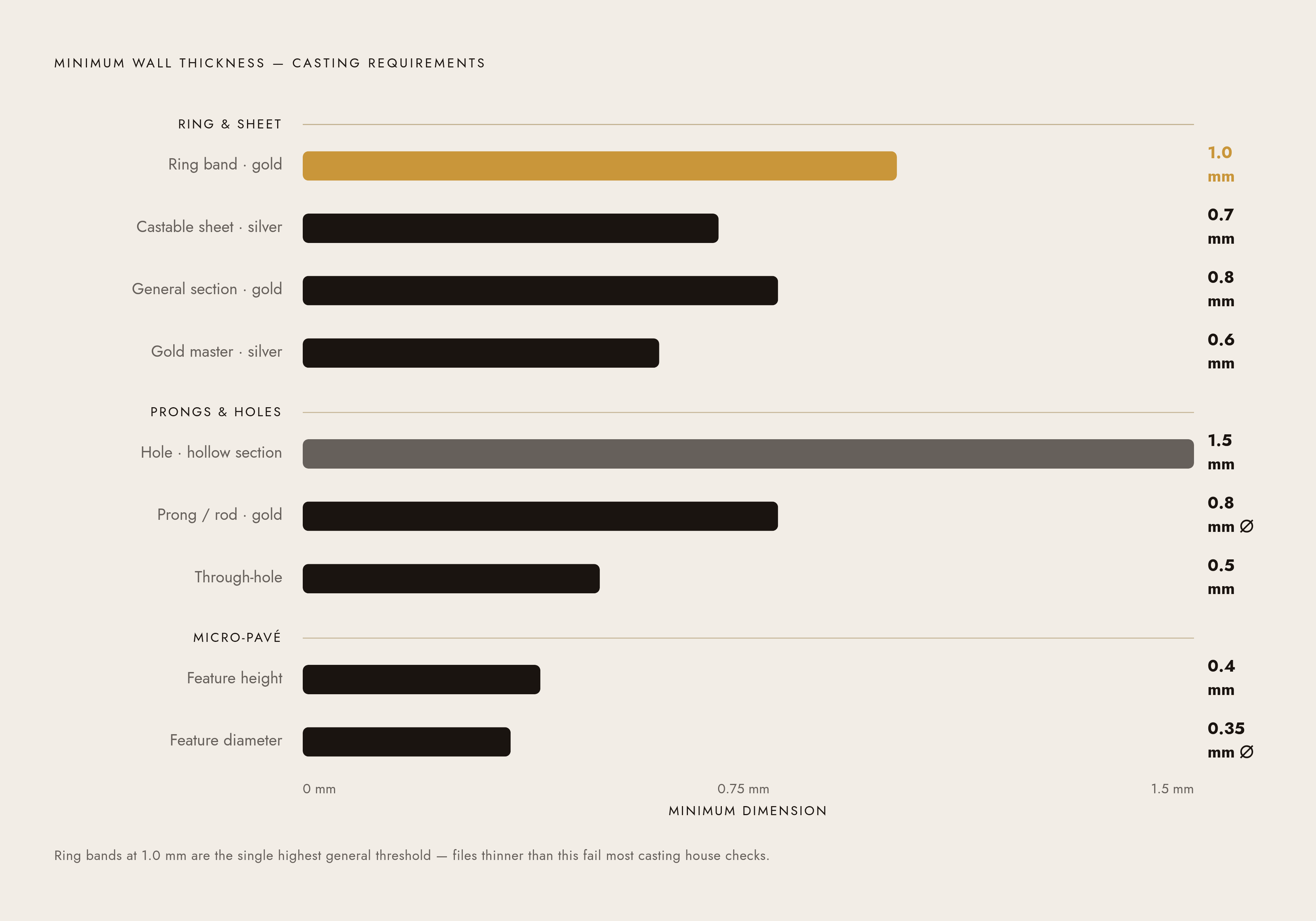
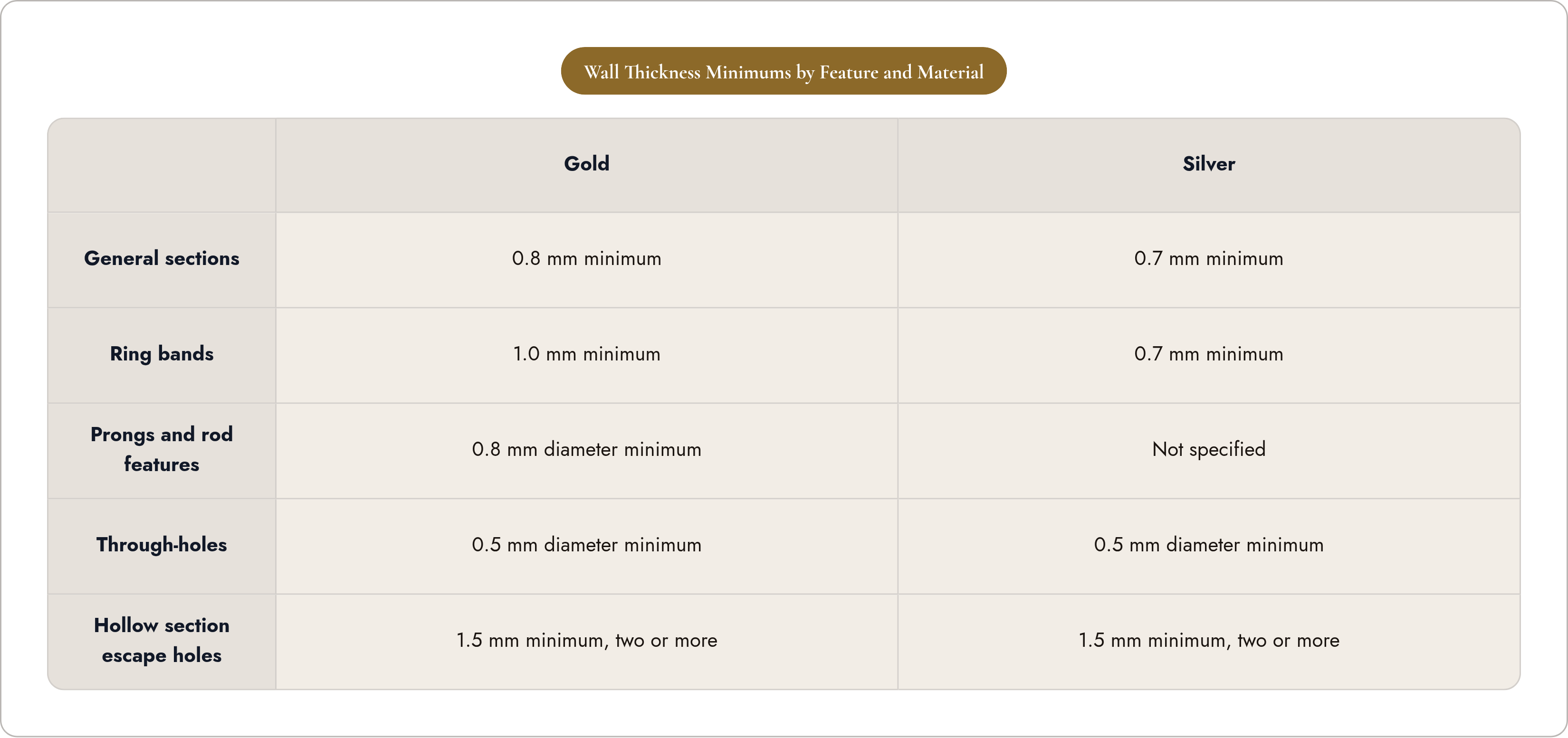
Here are the numbers that actually matter in production:
- Gold: 0.8 mm minimum for most sections. Ring bands need at least 1.0 mm. Thinner gold bands risk breaking in wear.
- Silver: 0.7 mm minimum for castable sheets. 0.6 mm for gold masters, which will yield 0.6 to 0.5 mm after filling and polishing.
- Gold prongs and rod features: 0.8 mm minimum diameter. Longer features are especially vulnerable because gold is not a particularly strong material.
The physics behind these numbers: liquid injection wax and liquid metal both have to flow to every part of the mold. Walls that are too thin either prevent flow or cause the metal to solidify before it fills the section, leaving incomplete castings or porosity.
Holes are their own category:
- Through-holes: 0.5 mm minimum diameter for practical production.
- Holes in hollow or thick sections: 1.5 mm minimum.
- Smallest printable features in micro-pavé contexts: roughly 0.35 mm diameter, 0.4 mm height. Only reliable when attached to a solid surface.
Pointed features are a systematic failure point. Surface tension of liquid metal prevents fill at very fine points. The fix is to model enough material at the tip and file it back after casting. Don't try to cast the final point. Cast something close and finish from there.
Hollow pieces need escape holes. At least two holes of 1.5 mm or larger, spread equally around the piece. This evacuates unprinted wax resin and provides support for the investment plaster.
Open-form rings (tension-set designs, one-size-fits-all styles) need a structural bridge bar of at least 1.0 mm across the gap. This improves cast fidelity significantly. The bar comes off at the finishing stage.
The wall thickness check is where the largest share of amateur files fail. Digital renderings look fine regardless of wall depth. The render doesn't care if your wall is 0.3 mm. The metal does.
Stone seat geometry and the dimensional data a caster needs alongside the file
Most casting houses require dimensional spec sheets alongside the file. The file tells them what to print. The spec sheet tells them what you're trying to make. Submit only a file with no spec data and most professional houses will treat it as an incomplete submission and send it back.
Required submission data typically includes: metal preference and karat, finger size, ring width at top and bottom, height at top and bottom, all stone sizes and the number of stones, metal weight, and the level of finishing desired.
Stone seat geometry gets its own close look. Seat diameter, depth, and girdle fit must be sized for the actual stone being set. Not an approximation. The actual stone. Prong placement, count, and positioning are reviewed for setting access after casting. Spacing between stones must allow the casting to survive intact and give the setter physical room to work.
A beautiful design that seats stones too shallow or places them too close together will fail at the setting stage even if the casting is perfect. The caster can get you a perfect cast. They cannot fix seat geometry after the fact.
Logos and engraved lettering need specific implementation to survive casting. Letter depth and stroke width matter. Appearance in the render is not the metric. Whether the detail survives the investment and the pour is the metric.
Draft angles on prong walls increase the contact area between the prong and investment and improve casting success rate. It's an easy detail to overlook in CAD. It's worth modeling correctly.
Shrinkage compensation and why dimensions in the file are not final dimensions
Most metals shrink 3% to 6% when transitioning from liquid to solid state. Without compensation for that in the CAD file, prongs come out looser than modeled, stone seats don't fit as intended, and bands measure short.
The specific shrinkage factor depends on the alloy and the production method. Silver, gold, and copper-based alloys all behave differently. Silicone molding, low-temperature vulcanization, and direct wax printing each introduce different variables. There is no single universal offset that covers all cases.
Fine surface detail (engraved text, filigree, texture) needs to be scaled up slightly in CAD so it remains visible after polishing removes material from the surface. This is a step that's easy to skip because the render looks sharp. The finished piece is the test, not the render.
The move here is straightforward: communicate desired final dimensions explicitly to the caster. Tell them the pendant height, band width, and charm thickness you want in the finished piece. Let them apply the correct offset before print. Don't assume the model dimensions are the target dimensions.
Shrinkage compensation errors compound with stone seat tolerances in a particularly painful way. A seat modeled to exact stone size, without any shrinkage offset, will be undersized after casting. The stone won't fit. You'll know exactly what went wrong and it will still be annoying.
On a first run of a new design, this is often worked out collaboratively between designer and caster. Which is exactly why clean communication at intake matters as much as the file geometry itself.
Sprue placement and how casting geometry shapes the intake review
The sprue is the gate through which molten metal enters the piece. Its placement determines whether metal reaches every extremity before it solidifies. Get it wrong and you get incomplete fills, porosity, or shrinkage voids in the worst spots.
Casting houses increasingly treat sprue placement as part of their pre-acceptance review. A poorly sprued file gets returned or flagged before production begins. This is not a cosmetic note. It's an engineering decision that affects yield.
Features that make metal flow difficult:
- Deep undercuts
- Long thin rods positioned far from the sprue
- Prong clusters at the end of narrow channels
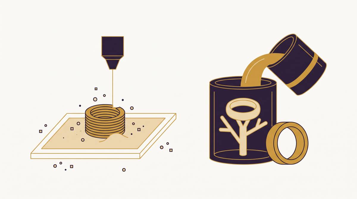
The lost-wax pathway runs like this: wax model, investment plaster, metal pour (by centrifugal force or vacuum). Every design decision in CAD either helps or fights the physics of that pour. Designers who understand sprue logic can model with casting in mind from the start rather than discovering the problem at submission. It's genuinely useful knowledge, and it shows in the files.
Draft angles on prongs and walls come back up here too. Increasing the angle of contact between prong geometry and investment improves casting success rate. It helps the metal fill cleanly and helps the investment release cleanly. Model it in. It takes less time than explaining why the prongs came out wrong.
Intellectual property compliance as a formal intake gate
Professional casting houses will not cast or copy copyrighted models unless the submitter can demonstrate they own the rights. This is stated policy at major houses, not an informal courtesy.
Houses also check that karat stamps are present and correct on the model before submission.
Copyright protection in jewelry is genuinely complex. Original artistic elements that are separable from the functional aspects of a piece are protected. Copyright terms extend 70 years beyond the creator's death. The U.S. Copyright Office has historically treated most fashion as functional and therefore unprotected, but jewelry occupies a contested gray zone. Multiple lawsuits over alleged jewelry design copyright infringement have been filed in recent years (Center for Art Law, July 2024).
The practical intake implication is simple: if your file is a reproduction of a named brand piece, or an existing design you cannot prove you own, a professional casting house will decline the work.
For designers using AI generation tools or design libraries, provenance of the CAD output matters. A design generated from a protected reference carries the same legal risk as a manual reproduction. "The AI made it" is not a rights clearance. That argument has not worked well for anyone so far.
What designing to the checklist from the start actually looks like
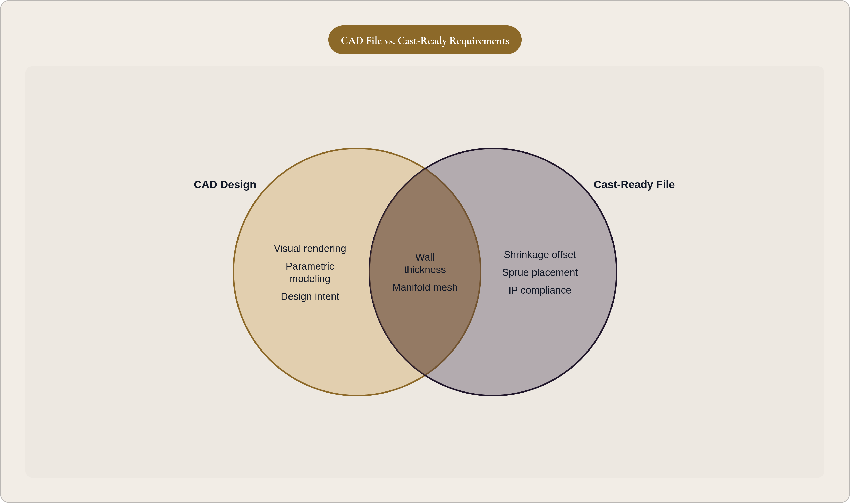
The checklist is not an external obstacle. It's the manufacturing constraint set that every production piece must satisfy. The designers whose files go straight to wax print are the ones who internalized that early.
Designing backward from the checklist looks like this:
- Wall thickness decisions made at the modeling stage, not patched at export
- Stone seats sized to actual stones with setting access modeled in
- Mesh unified before file review, not assembled from floating parts
- Export settings verified for unit, scale, and shell count
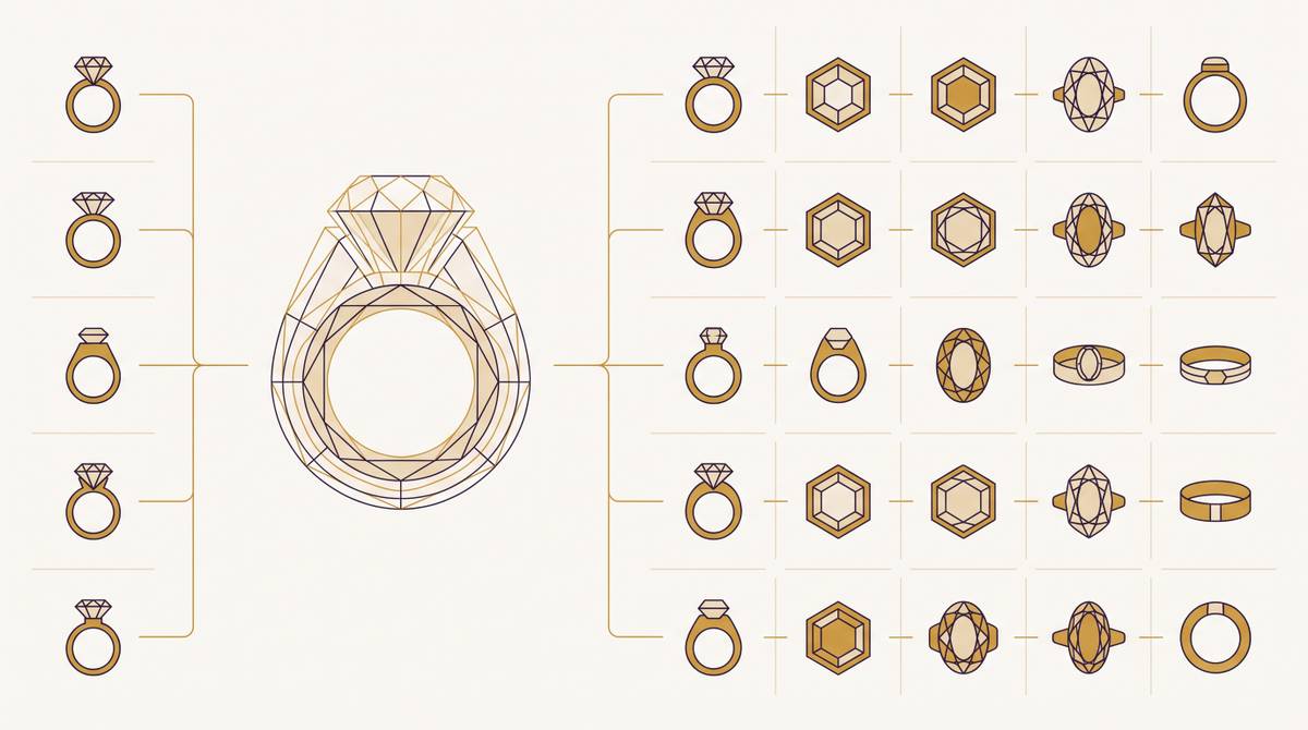
Parametric and AI-native design tools can encode these constraints as rules rather than manual checks. Wall thickness floors, hole size minimums, boolean unification. Files that are structurally valid by construction rather than by luck.
The production timeline matters here too. Standard production runs at many houses sit in the range of several weeks. Some shops advertise fast turnaround on CAD-approved files. A single rejection and rework cycle can eat a significant portion of total lead time before the piece ever gets printed. That math gets old fast.
For designers managing multiple SKUs or running made-to-order configurations, building castability into the design system is the difference between a scalable workflow and a recurring bottleneck. Verifying file-by-file after modeling is the slow version. Building it in from the start is the fast version. One of those feels like quality control. The other one just feels like quality.