Quality Control Checkpoints for AI-Generated Jewelry CAD Files
Catch mesh errors and wall-thickness failures before casting costs the real money.

AI has made custom jewelry CAD fast. Genuinely, surprisingly fast. What used to take a professional modeler eight to sixteen hours can now happen in minutes. That's not an exaggeration. It's not a marketing claim. It's just where the tools are right now.
But here's the thing nobody puts in the headline: speed only matters if the file is actually castable.
A fast file with a hole in its mesh, walls too thin to survive burnout, or prong tips sized to look good on a screen rather than fold over a real stone is not a time-saver. It's a problem with a head start — like handing someone a map with the destination already circled but the roads drawn wrong. The production pipeline is interconnected. A decision made in CAD, whether that's band thickness, seat depth, or prong length, propagates forward through casting, setting, and finishing. Errors caught in the file cost almost nothing. Errors caught at the bench cost material, labor, and time. Errors that slip through reach the customer.
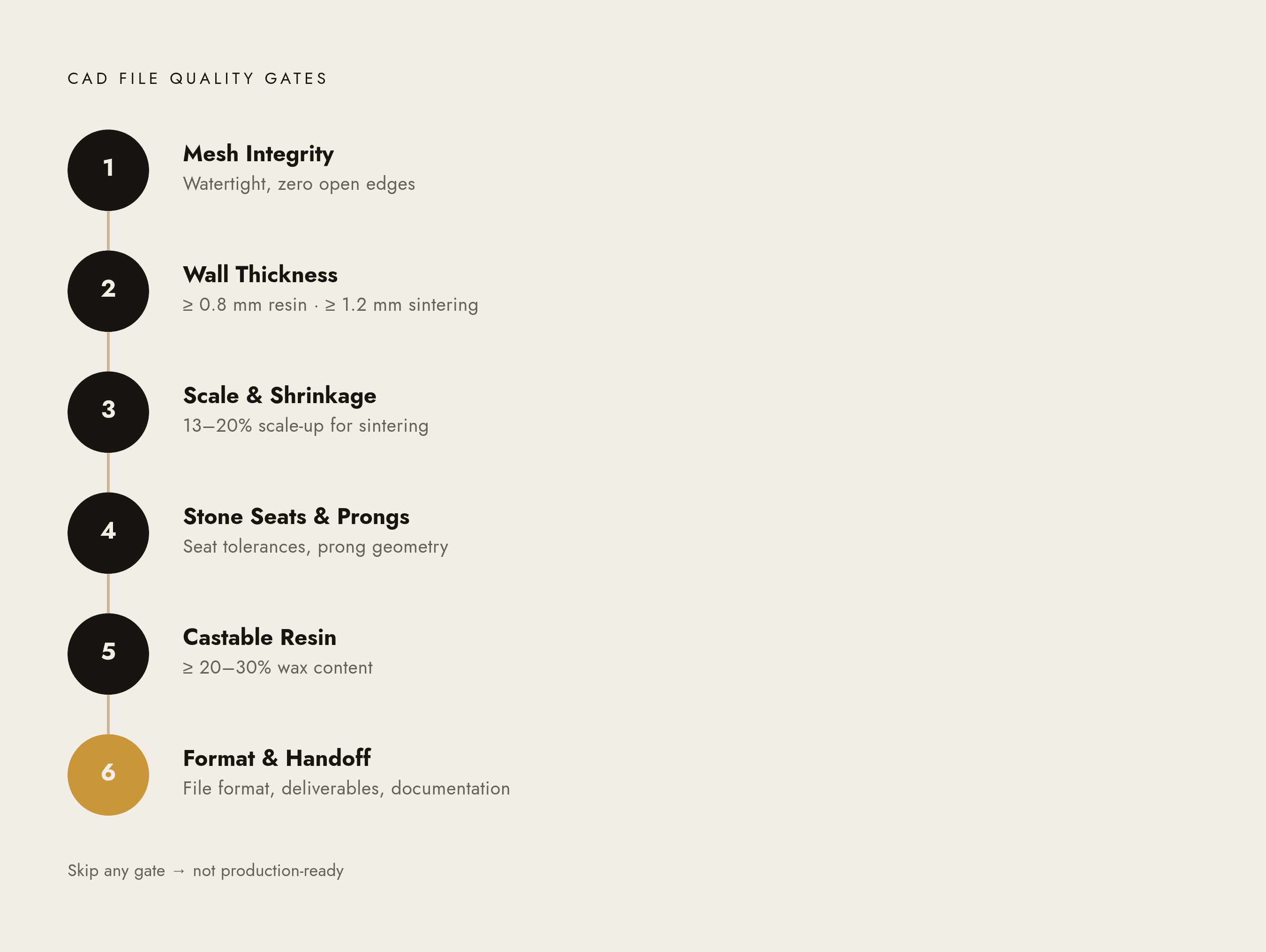
"Production-ready" means more than visually correct. It means structurally sound, dimensionally accurate, and format-complete for the caster's workflow. The six checkpoints below cover exactly that. Run them before any AI-generated file leaves your hands.
What AI Tools Actually Produce (And Where Things Go Sideways)
Not all AI design tools produce the same kind of output, and that distinction matters before you can QC anything.
On one end, you have generative image tools. They produce concept visuals, not geometry. Beautiful, useful for ideation, not castable in any direct sense. On the other end, you have AI-assisted parametric platforms that output editable CAD files, and fully automated brief-to-3D-model pipelines that take a text or image prompt and return a mesh file. The middle and far end of that spectrum are where production files come from.
The output format is as important as the output quality:
- STL: Triangle-mesh format. The most common handoff to manufacturers. Used for 3D printing and casting prep.
- 3DM: Retains editability. Useful when the caster or bench jeweler needs to make adjustments after the file arrives.
- OBJ: Less common in production. More typical for visualization purposes.
AI generation is genuinely good at collapsing the concept-to-first-model phase. The problem is that automated mesh generation doesn't carry the judgment a trained CAD modeler applies about castability. A trained modeler is thinking about burnout, about setter access, about whether that prong tip will survive being pushed over a girdle. The AI is solving a geometry problem.
The failure modes that show up most often in AI-generated files:
- Non-manifold geometry: The mesh looks closed in the preview. It isn't.
- Undersized prongs and settings: Proportioned to render well, not to survive casting or setting.
- Stone seats sized by eye: Visually plausible, dimensionally wrong.
- Unit and scale errors: The file inherits the generation environment's coordinate system, not a manufacturing one.
Parametric platforms that maintain the design as structured parameters rather than a raw mesh reduce several of these risks. When a dimension changes, the geometry updates consistently. That's a meaningful difference from a mesh that was generated once and can only be repaired after the fact.
Checkpoint 1: Mesh Integrity and Watertight Geometry
This is the first check, and it's non-negotiable.
A watertight mesh, sometimes called a manifold mesh, means every edge in the model is shared by exactly two faces. The surface is fully closed. No holes, no gaps, no overlapping surfaces. It's the geometric equivalent of a sealed container — if there's a breach anywhere, the whole thing is compromised. If the mesh has a breach anywhere, the printer or slicer can't determine what's inside the model versus what's outside. The print fails, or worse, it completes in a way that looks fine until the casting comes back wrong.
Common mesh errors in AI-generated STL files:
- Holes: Open edges where faces are simply missing.
- Inverted normals: Faces pointing the wrong direction. The software gets confused about which side is the exterior.
- Non-manifold edges: Edges shared by more than two faces. Physically impossible geometry.
- Overlapping or self-intersecting faces: Two surfaces trying to occupy the same space.
These errors are invisible in a standard render. A model can look perfect in a preview and have a dozen mesh problems underneath.
The tools for catching and fixing this are Netfabb and Meshmixer. Both are standard in production workflows. Netfabb validates against formal mesh integrity definitions, so when it clears a file as watertight, that's a real compliance pass, not just a visual check.
Practical protocol:
- Import the AI-generated file into a mesh repair tool before it goes anywhere else.
- Do not rely on the generation platform's own preview. Visual correctness in a renderer does not mean mesh correctness.
- Log any repairs made so the master file reflects the corrected geometry, not the original flawed version.
Checkpoint 2: Wall Thickness Across Every Section of the Piece

Minimum wall thickness is the most critical design-for-manufacturability consideration in jewelry CAD. It is also one of the most consistent failure points in AI-generated files.
The numbers you need to know:
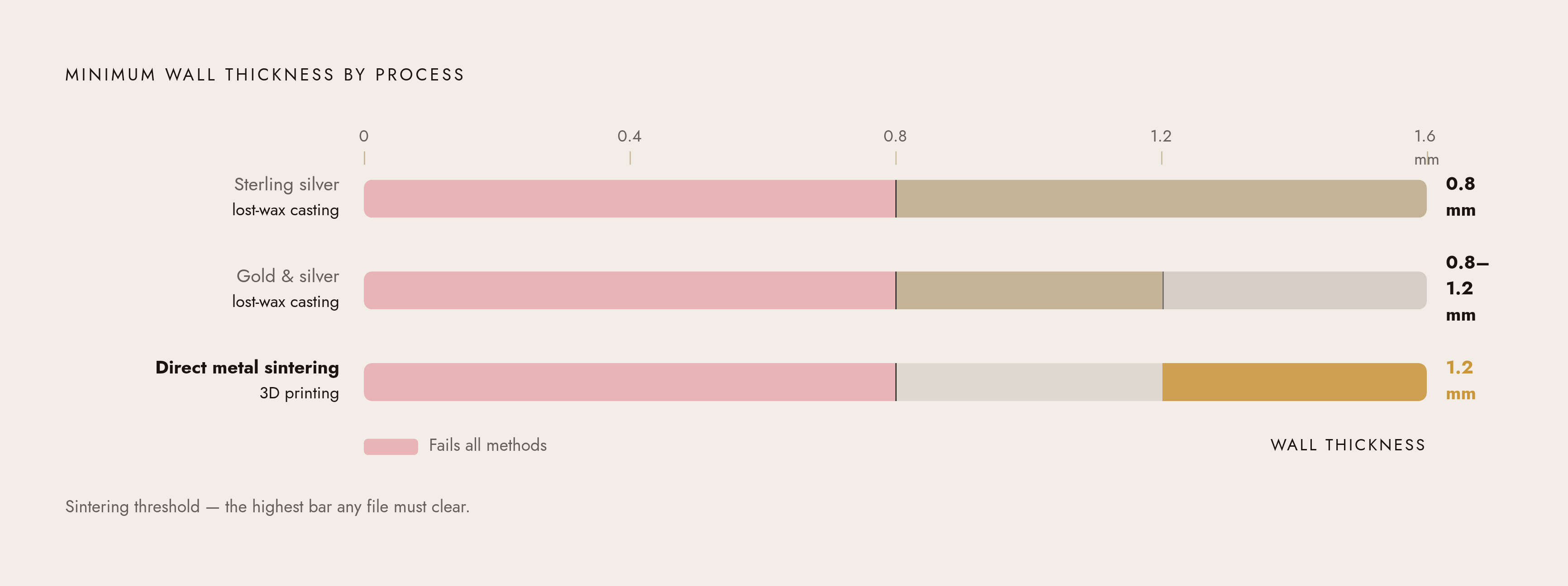
- Resin casting (gold, silver via lost-wax): Walls must be at least 0.8 to 1.2 mm. Thinner than that and the piece will crack during burnout or collapse during the pour.
- Sterling silver specifically: 0.8 mm is the recommended minimum. Anything thinner is prone to breaking and will not cast cleanly.
- Direct 3D metal printing (sintering): Minimum wall thickness rises to 1.2 mm.
AI generation produces walls that look substantial in a render. In cross-section, they're often below threshold. Filigree, delicate shanks, and prong tips are the usual failure points. They look elegant. They don't survive.
How to check: Import the file into a slicer or analysis tool and run a wall-thickness heat map. Any region below the applicable minimum gets flagged. This is not a visual review. You need the measurement.
Decisions at this stage are straightforward:
- Thicken the wall in the CAD model and re-export.
- If thickening changes the design intent, flag for designer review before the file moves forward. Don't silently fix something that changes what the client approved.
- Document the minimum thickness achieved in the released file, alongside the material specification it was checked against.
Checkpoint 3: Scale, Units, and Shrinkage Compensation
Unit mismatch is a catastrophic error. A ring modeled in inches but interpreted by the printer in millimeters produces a piece roughly 25 times oversized. This is not a hypothetical. It happens.
Jewelry CAD must be modeled at real-world dimensions, accurate to fractions of a millimeter. The standard is millimeters, file scaled to 100%, explicitly verified before export. Not assumed from the platform default. Verified.
Shrinkage compensation is a separate issue and equally important. Metal contracts during sintering and casting. The model must be scaled up before it goes to the caster to account for that contraction.
- For metal sintering workflows, scale up somewhere in the range of 13 to 20%, depending on the alloy.
- That range is wide because alloys and post-processing methods differ. Confirm the exact compensation factor with your caster before finalizing. Don't guess.
For STL export settings that preserve dimensional fidelity, use a chordal tolerance of 0.1 mm, angle deviation of 1 to 5 degrees, and a max edge length of 0.5 mm. This produces a mesh resolution that holds fine detail without inflating file size unnecessarily.
The practical check here is simple: measure a known dimension in the exported file using the caster's preferred tool. Ring inner diameter, shank width, overall height. Confirm it matches the design spec. If it doesn't, find out why before the file ships.
Checkpoint 4: Stone Seat Tolerances and Prong Geometry
This checkpoint is where jewelry-domain knowledge becomes non-negotiable. Generic 3D print prep tools won't catch these errors. There's no algorithm checking whether a prong is long enough to fold over a girdle.
Stone seats in AI-generated files are frequently sized to look correct in a render. The visual and the physical are not the same thing. Every seat must be verified against the actual stone it will hold.
What that means in practice:
- Seat diameter and depth must match stone calibration within the tolerance the setter requires. Not approximately. Within tolerance.
- Girdle depth determines whether the setting will hold the stone securely once it's set.
- Bezel height must be tall enough to fold over the girdle without cracking.
Prong geometry problems from AI generation cluster around the same issues. Prongs that are too short to fold over the stone's girdle. Prongs that are too thin to survive the bending force without snapping. Prongs spaced in a pattern that looks symmetric but won't actually hold the stone.
Pavé and pavé-adjacent settings have their own failure mode. AI-generated pavé patterns often look correct as a surface texture. The shared prong or bead geometry is not mechanically viable when you look at whether it can physically separate and hold adjacent stones.
The verification approach: run the seat dimensions against the stone spec sheet. If the platform is parametric, update the seat parameter to the measured stone size and re-export. Do not hand-edit the mesh to fix a tolerance issue. That approach introduces new geometry problems faster than it solves the existing one.
Checkpoint 5: Castable Resin and Material-Specific Output Requirements
Standard modeling resin leaves carbon residue during burnout. That residue contaminates the molten metal and causes pitting and porosity in the finished casting. The piece looks fine until it doesn't.
For lost-wax casting via 3D-printed resin, castable resin with a wax content of at least 20 to 30% is required. It needs to burn out cleanly in a kiln without ash. That's a material specification, and the CAD file needs to be designed with that material in mind.
Specific considerations for the file:
- Wall thickness minimums differ between display resin (can be thinner) and castable resin (0.8 to 1.2 mm minimum). A wall that prints fine for a display model will not survive the castable resin process.
- Support structure geometry for SLA and DLP printing must be accounted for in the file. Some geometries trap supports in locations where they can't be removed cleanly.
- Overhangs and lattice structures that print successfully in standard resin will fail in castable resin due to different material properties.
On the SLA versus DLP question: both are standard in jewelry prototyping. SLA cures layer by layer with a UV laser, which produces high surface quality and fine detail. DLP uses a projected light source, which is faster with comparable resolution for most applications. Confirm which technology your caster uses. The file's resolution settings should match the print technology, not the generation platform's defaults.
For the file record, document which resin type and print technology the file was validated for. A file cleared for one process is not automatically cleared for a different one.
Checkpoint 6: File Format, Deliverable Completeness, and Handoff Documentation
Format selection is a deliberate decision, not a default you accept because that's what exported.
- STL: Appropriate when the caster will print directly and no further editing is expected.
- 3DM: Appropriate when the caster or bench team need to make adjustments. Retains editability.
Confirm the caster's preferred format before finalizing export settings. Some casters have a strong preference. Some workflows require one format and won't accept the other.
A complete handoff package contains:
- The primary CAD file in the agreed format
- A dimensional spec sheet: ring size, key measurements, shrinkage compensation factor applied
- Stone specifications: size, shape, and quantity for every setting in the piece
- Material specification: alloy, intended casting method
- A QC sign-off log noting which checkpoints were run, which tools were used, and what (if anything) was repaired or modified
The log is the piece most people skip. It's also the piece that saves the most time when something goes wrong. If a casting comes back with a defect, the QC log tells you immediately whether the problem originated in the file or in the casting process. Without it, every failure investigation starts from zero. Every single one.
For teams using a platform that claims to output production-ready files directly: confirm that the platform's export pipeline actually applies shrinkage compensation and format settings automatically. Verify that it does. Don't assume it does because the marketing says so.
How to Build These Checkpoints Into Your Workflow Without Adding a Day to Every Project
The checkpoints above are not meant to be a manual waterfall you run sequentially on every file from scratch. That would be slow and you wouldn't do it. They work best as defined gates embedded into the workflow at specific moments.
A practical integration pattern:
- Automated mesh check on every file export. This takes seconds. It catches the most common AI generation artifacts before a human reviews the file. There's no reason not to run it every time.
- Wall thickness and dimensional analysis before client review, not after. Presenting a design that will require structural changes post-approval is a painful conversation. Catch it earlier.
- Stone seat and prong review after design approval but before final export. This checkpoint requires the stone specification to be confirmed first. You can't verify a seat against a stone that hasn't been selected.
- Material and format sign-off as part of the release checklist. Not a separate step you remember to do sometimes.
Parametric platforms reduce the rework burden meaningfully. When a stone size changes, the seat geometry updates automatically. That's very different from manually editing a mesh after the fact, which introduces new problems as often as it solves old ones.
The designers getting the most out of AI tools right now are the ones who have collapsed the disconnected steps into a single workflow. File review in one tool, spec documentation in a spreadsheet, format conversion in another, mesh repair somewhere else. That's friction. QC checkpoints embedded directly into the workflow add almost none.
One last thing worth saying plainly: the caster's requirements don't change based on how the file was made. They don't care whether a human modeler spent twelve hours on it or an AI generated it in forty-five seconds. The file either meets spec or it doesn't. These checkpoints exist to make sure it does. A file that skips QC is a lot like a ring without a setting — it looks complete, but it won't hold under pressure.