Wax Printing Specifications for Jewelry CAD Files
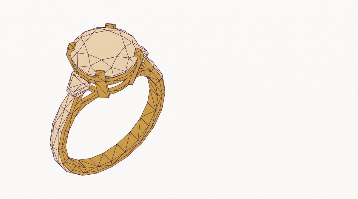
Mesh quality is the foundation—fix it before worrying about anything else.
Before thickness, before tolerances, before any of the fun stuff. The mesh has to be right. Everything else depends on it. A broken mesh cannot be accurately evaluated for anything. Fix this first, full stop.
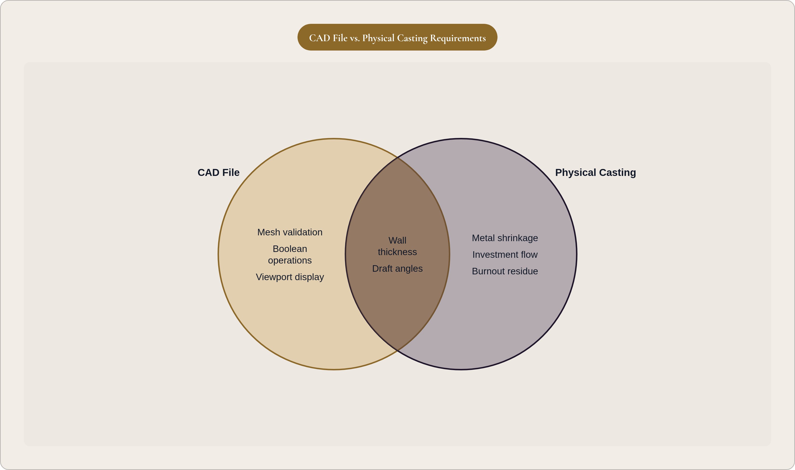
Two terms that matter:
- Watertight. The model is a completely closed volume. No holes, no open edges, no gaps between surfaces. Picture pouring water into the model as if it were a container — none should leak out.
- Manifold. Every edge is shared by exactly two faces. Not one (an open gap). Not three (overlapping walls). No inverted normals, no duplicate faces stacked on top of each other.
Here is what happens when this goes wrong. One bad boolean operation (a subtraction that did not close cleanly) leaves a naked edge. The slicer misreads it. What you get in the wax is a void where solid geometry should be, or a collapsed wall where the printer could not determine inside from outside. The printer does not guess. It does not round up. It does not give you the benefit of the doubt. It builds exactly what you gave it, broken geometry and all. I have seen beautiful ring designs come out of the printer looking like someone took a bite out of them because of one unresolved boolean that looked fine in the viewport — you could say the design had a hole in its story.
That last point is the thing that gets people. A file can look perfect on screen and still fail mesh validation. The visual display in most CAD software is forgiving in ways the slicer simply is not. Always run a mesh analysis before submitting. The viewport is not the source of truth. The mesh analysis is.
Accepted export formats:
- STL — industry standard, most universal. Use this unless you have a specific reason not to.
- OBJ — widely accepted, carries UV data, no casting advantage over STL.
- STEP, IGES, 3DM, STP, SKP, SLDPRT, WRL — many production platforms accept these. Useful when the file originates in parametric CAD and you want to preserve exact geometry before tessellation.
What to check before export:
- Naked edges or open polysurfaces? Close them.
- Bad booleans? Re-run the operation or rebuild the union entirely.
- Non-manifold geometry? Find it in a mesh repair tool and fix it.
- Inverted normals? Flip the surfaces so everything faces outward.
Wall Thickness Minimums by Metal and Application
Wall thickness is a casting survival spec, not just a printing one. A wall that prints fine in wax can collapse when liquid metal fills the mold. Think of the wax as a rough draft and the metal as the final exam — the wax is soft and cooperative; the metal is neither.
Minimums by metal:
- Silver: 0.8–1 mm minimum. Silver shrinks more than gold during solidification, which puts extra stress on anything thin.
- Gold: 0.8 mm general minimum. Ring bands specifically should be at least 1 mm.
- Daily-wear ring bands: Most workshops I have worked with hold 1.5 mm as the functional floor. A band can survive the casting and still fail six months later from mechanical wear if it started thin.
Application-specific targets:
- Prongs: 0.6 mm minimum diameter. Thinner than that and they will not survive setting, let alone daily wear.
- Earring posts: 0.8 mm minimum.
- Stone seat depth: At least 0.7 mm below the stone table. Less and the setting will not hold after the setter works it.
- Through-holes: 0.5 mm minimum diameter for reliable results through both printing and casting. Smaller holes are a gamble.
Clearances between parts deserve their own mention. If the gap between two surfaces is too small, two things go wrong. Parts can fuse during casting. And investment plaster cannot flow fully into the mold cavity, which creates thin mold walls that fracture under the metal pour. Both outcomes ruin the piece, and neither is recoverable after the pour.
Build these minimums into the design file as hard constraints from the start. Finding an under-thick wall after rendering means you have already wasted a design iteration.
Shrinkage Allowances and Dimensional Tolerances the File Must Pre-Compensate
The CAD file should model a geometrically compensated version of the finished piece, not the finished piece at exact target dimensions. That distinction sounds small. In practice it is the difference between a ring that fits and one that does not.
Two distinct sources of dimensional change:
- Metal shrinkage during solidification. Approximately 1.5% for gold, approximately 2% for silver. The metal pulls inward as it cools. A ring modeled at exact finished size will cast undersized, every time.
- Post-casting bench work. Filing and polishing remove thin layers of metal. A 0.25 mm buffer built into the model preserves target dimensions after the bench jeweler finishes the piece.
The correction is to scale the CAD model up by 1.5% to 3% before exporting, depending on the metal. Your foundry will give you a more precise number based on their specific process. Use their number. But scaling is not optional.
Stone seats are the least forgiving spec in the file. A deviation of ±0.03 mm can cause a gem to sit loose or crack under setting pressure. The seat diameter should be modeled 0.05–0.1 mm smaller than the actual stone diameter. That intentional undersize gives the setter material to work against. For diamonds, some setters want it even tighter. Ask before you finalize.
Prongs should be modeled longer and thicker than the finished piece will show. The extra material is what the bench jeweler cuts and bends over the stone. Without it, the prongs come out too short to set. This is not an aesthetic choice. It is a functional requirement.
High-precision MJP equipment holds dimensional accuracy of ±0.04 mm per 20 mm. The printer is usually not the primary source of dimensional error. Under-compensated shrinkage in the file is. Many production houses enforce a ±0.05 mm tolerance standard across custom CAD models. That is a reasonable target to design toward.
Layer Height Settings and How They Map to Detail Levels in the Final Piece
Layer height is a printer setting, not a file property. But which setting is appropriate depends entirely on what is actually in the file.
Practical tiers:
- 25–50 microns: Fine for most ring shanks, flat surfaces, and simple pendants. Faster print time. Acceptable surface quality for geometry without fine detail.
- 10–25 microns: Required for micro-pavé, sharp engraving, milgrain, and filigree. At this resolution, detail that exists in the file actually shows up in the wax.
- 25 microns: A solid default for jewelry models with significant fine detail.
Stair-stepping is the thing people consistently underestimate. At 25–30 micron layers, curved surfaces (rings, domes, anything organic) show visible stepping. The surface looks smooth in the CAD viewport. It does not look smooth in the wax if the layer height is too coarse. And here is the part that matters: the surface finish of the wax sets the surface finish of the casting. A stair-step in the wax becomes a stair-step in the metal — like a bad rumor, it follows the piece all the way to the finished product. A polisher can remove it, but on a piece with fine detail, polishing that aggressively means losing the detail you spent hours modeling.
Match the layer height to the finest feature in the file. If the file has micro-pavé seats and the job prints at 30 microns, the seats will not resolve correctly. If the file is a simple flat band, printing at 10 microns just costs more time and money with no visible benefit.
On support contact points: for jewelry, support nubs should be 0.3–0.4 mm. Fine enough to snap off cleanly. Orient the model so supports land on unexposed areas. Not on prong tips. Not on table surfaces. Not anywhere that will show on the finished piece.
Draft Angles, Undercuts, and Geometry That Cannot Survive the Investment Mold
This is where designers get surprised. The wax prints beautifully. The casting comes back wrong. And it takes a beat to realize the problem was baked into the geometry from the beginning.
Draft angles. Any surface running perpendicular to the mold parting line needs at least 5 degrees of angle. Without it, the cast piece cannot release from the investment without tearing or distorting. The mold just grips it.
Undercuts. Geometry that overhangs itself in a way that traps investment plaster is not castable. It does not matter how cleanly it prints. When the mold breaks open, the piece does not come out intact. Catching this in CAD costs nothing. Discovering it after the pour costs the entire casting plus the time waiting for the result.
Investment plaster behavior matters here too. If a cavity or channel is too narrow, liquid investment cannot flow in completely. It leaves an air pocket. That air pocket fills with metal during the pour. Not as solid structure. As porosity. The piece looks solid and is not.
Burnout ties into this in a way designers do not always connect. Carbon residue left in the mold from an incomplete burnout creates surface porosity (little pits that show up after polishing). The design of the wax model affects burnout quality directly. Wall proximity, channel width, overall mass distribution: these determine how cleanly the wax burns away. It is not just a furnace setting issue. It is a design issue.
One more thing worth understanding: wax models attach to the central sprue at roughly a 45-degree angle. Lighter, more delicate pieces go near the top of the tree; heavier pieces toward the base. The CAD designer does not control tree placement, but understanding it helps when thinking about sprue attachment points and mass distribution in the piece.
If you cannot explain a geometry feature in terms of how metal will fill it and how the mold will release it, that feature is probably not castable.
Environmental and Material Conditions That Affect Whether a Correct File Prints Correctly
You can submit a perfect file and still get a bad wax. The file is one variable. The machine environment is another, and it does not care how much time you spent on the model.
Castable wax materials are highly viscous and temperature-sensitive. The printing environment should stay between 25°C and 30°C. Below that range, viscosity increases, flow rate drops, and fine features do not fill completely. The printer runs the job. The output does not match the geometry. Fine prongs come out thin. Pavé seats come out partially formed. The file was correct. The environment was not. I have seen this happen in shops that were otherwise meticulous about their CAD work (the problem was a cold morning and no one had thought to check the room temperature before starting the run).
On material selection: photopolymers formulated with 20%–40% wax content burn away cleanly during burnout, leaving zero ash residue. Lower-wax formulations can also work, but the right choice depends on piece complexity and the foundry's specific burnout schedule. Any residue left in the mold after burnout embeds in the cast surface as porosity. In intricate areas, it cannot be polished out without damaging the surrounding detail.
If you are using an external print service:
- Ask what temperature controls they maintain in the print environment.
- Ask what material they use and what the wax content is.
- A correct file on a cold machine with the wrong resin produces an inferior casting. File quality does not compensate for process quality.
If you run in-house printing:
- Machine maintenance, temperature consistency, and material batch quality all live outside the CAD file.
- They determine whether the precision you built into the model is actually realized in the wax.
The Pre-Export Checklist That Turns a Designed File Into a Submittable One
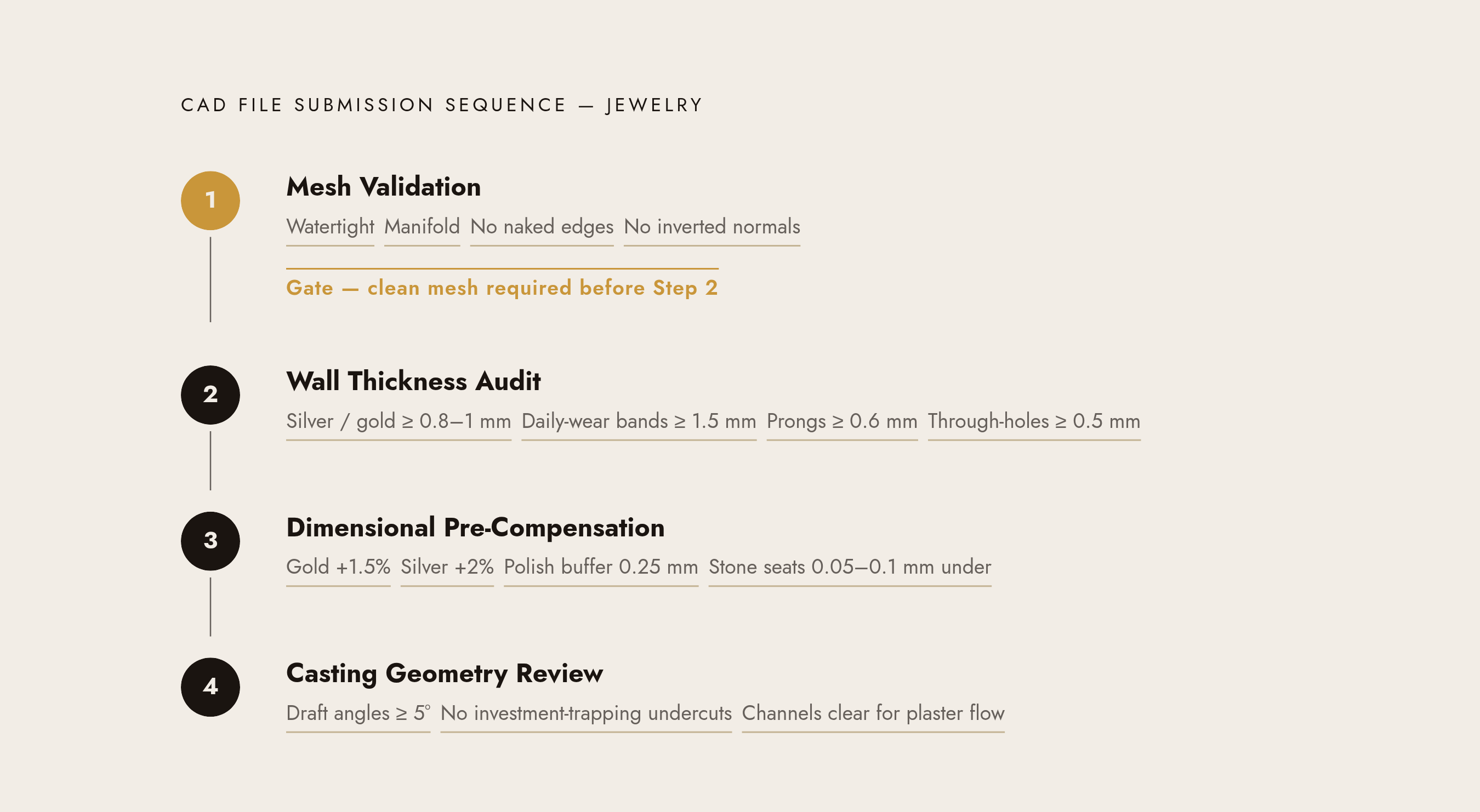
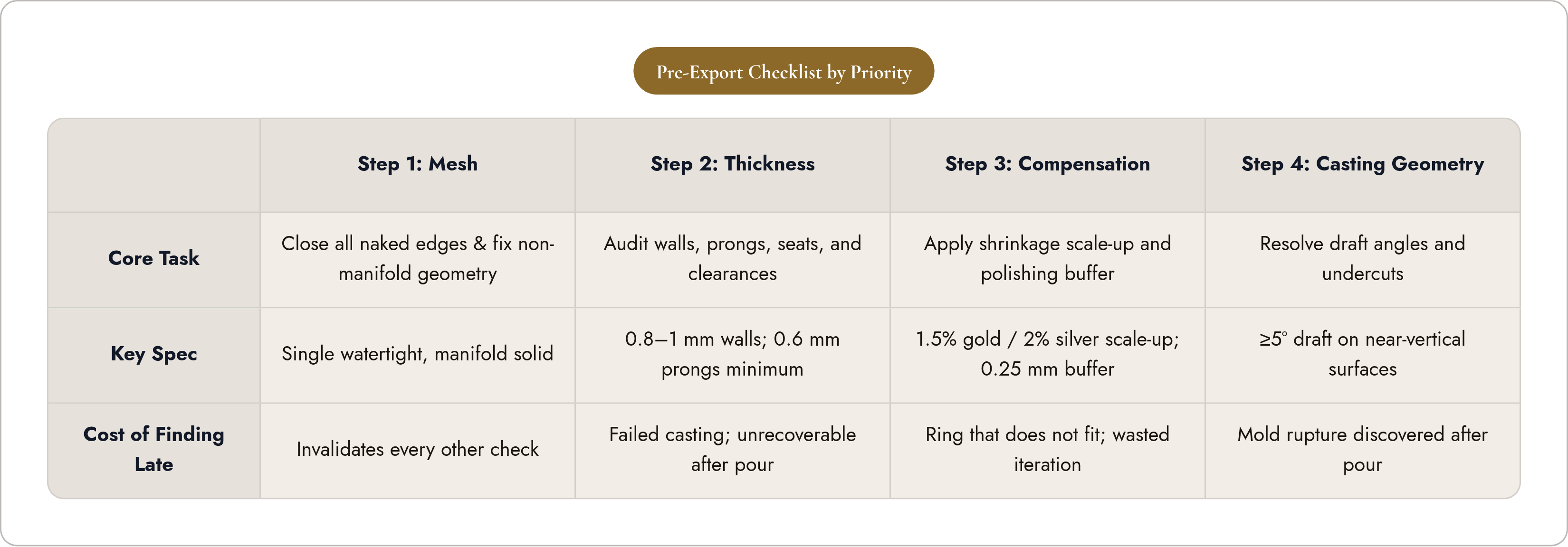
This is the sequence in which to catch problems, ordered by what it costs to find them late.
Step 1. Mesh Validation
- Run mesh analysis. Find and close naked edges. Fix non-manifold geometry. Resolve inverted normals.
- Confirm the model is a single closed, watertight solid.
- Do not move to Step 2 until this is clean.
Step 2. Wall Thickness Audit
- All walls meet metal-specific minimums: 0.8–1 mm for silver, 0.8–1 mm for gold, 1.5 mm for daily-wear bands.
- Prong diameter ≥ 0.6 mm.
- Earring post ≥ 0.8 mm.
- Stone seat depth ≥ 0.7 mm.
- Through-hole diameters ≥ 0.5 mm.
- All clearances between parts allow investment flow and prevent fusion.
Step 3. Dimensional Pre-Compensation
- Apply shrinkage scale-up: 1.5% for gold, 2% for silver (or use the foundry's specific number).
- Add 0.25 mm buffer on surfaces that will be filed and polished.
- Stone seats modeled 0.05–0.1 mm undersized relative to actual stone diameter.
- Prongs modeled with setting allowance (longer and thicker than the finished dimension).
Step 4. Casting Geometry Review
- Near-vertical surfaces have draft angle ≥ 5 degrees.
- Undercuts that would trap investment plaster are resolved.
- Channel widths and cavity depths allow investment flow and full metal fill.
Mesh first, because nothing else can be accurately evaluated on a broken mesh. Thickness second, because a thin wall is cheaper to fix in the file than in a failed casting. Compensation third, because scale and tolerance errors are invisible until the piece is on a mandrel and comes up short. Geometry last, because draft and undercut issues are the ones most likely to survive all the other checks and still blow up at the mold stage.
A file that clears all four steps is a submittable file. It is not a guarantee the casting will be perfect (too many variables live downstream of the file for that). But it is a guarantee the CAD stage is not the reason it fails.